- 您现在的位置:买卖IC网 > Sheet目录471 > MAX2015EVKIT (Maxim Integrated)EVAL KIT FOR MAX2015
�� �
�
 �
�MAX2015� Evaluation� Kit�
�Shutdown� Mode�
�TRANSMITTER�
�POWER�
�AMPLIFIER�
�GAIN-CONTROL�
�INPUT�
�COUPLER�
�The� EV� kit� is� configured� with� the� shutdown� feature� dis-�
�abled.� To� use� the� shutdown� feature� first� remove� R5.�
�Drive� PWDN� with� a� logic-low� (0V)� for� normal� operation�
�or� a� logic-high� (VCC)� to� place� the� device� in� shutdown�
�mode.� Leave� the� VCC� power� supply� on� and� turn� off� the�
�RF� power� when� switching� the� shutdown� pin.�
�Layout� Considerations�
�LOGARITHMIC�
�IN�
�A� good� PC� board� is� an� essential� part� of� RF� circuit�
�OUT�
�DETECTOR�
�design.� The� MAX2015� EV� kit� PC� board� can� serve� as� a�
�SET-POINT�
�DAC�
�SET�
�20k� Ω�
�guide� for� laying� out� a� board� using� the� MAX2015.� Keep�
�the� input� trace� carrying� RF� signals� as� short� as� possible�
�to� minimize� radiation� and� insertion� loss� due� to� the� PC�
�board.� Each� power-supply� node� on� the� PC� board�
�should� have� its� own� decoupling� capacitor.� This� mini-�
�mizes� supply� coupling� from� one� section� of� the� PC� board�
�20k� Ω�
�MAX2015�
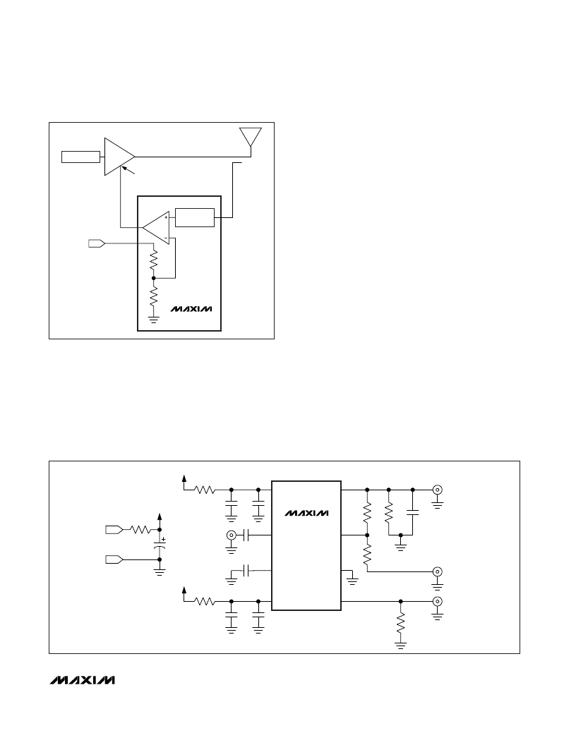
�Figure� 2.� MAX2015� in� Controller� Mode�
�Controller� Mode�
�For� operation� in� controller� mode,� remove� R1� and� set� R6� to�
�0� Ω� .� Use� a� DAC� or� external� precision� voltage� supply� to�
�apply� the� set-point� voltage� to� the� VSET� SMA� connector.�
�RF_IN� is� connected� to� the� RF� source� (power� amplifier�
�(PA)� output� through� a� directional� coupler)� and� VOUT� is�
�connected� to� the� gain-control� pin� of� the� PA� (see� Figure� 2� )� .�
�V�
�to� another.� Using� a� star� topology� for� the� supply� layout,�
�in� which� each� power-supply� node� in� the� circuit� has� a�
�separate� connection� to� the� central� node,� can� further�
�minimize� coupling� between� sections� of� the� PC� board.�
�Modifying� the� EV� Kit�
�The� EV� kit� design� includes� some� additional� resistors� (R2,�
�R3,� R4)� to� provide� for� possible� power-supply� filtering� and�
�for� high� power-supply� voltage� operation.� For� operation�
�where� V� CC� =� 2.7V� to� 3.6V� (TP1),� set� R4� =� 0� Ω� .� For� opera-�
�tion� where� V� CC� =� 4.75V� to� 5.25V,� set� R4� =� 75� Ω� ±1%�
�(100ppm/°C� max)� and� connect� PWDN� to� GND�
�(required).� The� output� load� for� VOUT� can� be� changed� by�
�including� the� values� for� R7� and� C8.�
�R2�
�1�
�V� CC�
�OUT�
�8�
�J2�
�SMA�
�VOUT�
�V�
�C6�
�C5�
�R1�
�R7�
�C8�
�TP1�
�V� CC� *�
�R4�
�J1�
�SMA�
�C1�
�2�
�INHI�
�MAX2015�
�SET�
�7�
�C7�
�RF_IN�
�TP2�
�GND�
�C2�
�3�
�INLO�
�GND�
�6�
�R6�
�J3�
�SMA�
�V�
�VSET�
�R3�
�4�
�V� CC�
�PWDN�
�5�
�J4�
�SMA�
�PWDN�
�C4�
�C3�
�R5�
�*V� CC� =� 2.7V� TO� 3.6V� WITH� R4� =� 0� Ω�
�V� CC� =� 4.75V� TO� 5.25V� WITH� R4� =� 75� Ω�
�Figure� 3.� MAX2015� EV� Kit� Schematic�
�_______________________________________________________________________________________�
�3�
�发布紧急采购,3分钟左右您将得到回复。
相关PDF资料
MAX2016ETI+T
IC DETECT/CNTRL LOG 28-TQFN
MAX2021ETX+T
IC MOD/DEMOD 36-TQFN
MAX2022ETX+T
IC MOD 1500MHZ TO 2500MHZ 36TQFN
MAX2022EVKIT
EVAL KIT FOR MAX2022
MAX2023ETX+T
IC MOD/DEMOD HI DYN RNG 36-TQFN
MAX2027EUP+D
IC AMP VAR GAIN 20-TSSOP
MAX2027EVKIT
EVAL KIT FOR MAX2027
MAX2029ETP+T
IC MIXER UP/DOWN HI LIN 20-TQFN
相关代理商/技术参数
MAX2016
制造商:MAXIM 制造商全称:Maxim Integrated Products 功能描述:Evaluation Kit
MAX20-16.0C
制造商:MDE 制造商全称:MDE Semiconductor, Inc. 功能描述:HIGH CURRENT TRANSIENT VOLTAGE SUPPRESSOR (TVS) DIODE
MAX20-16.0CA
制造商:MDE 制造商全称:MDE Semiconductor, Inc. 功能描述:HIGH CURRENT TRANSIENT VOLTAGE SUPPRESSOR (TVS) DIODE
MAX2016_06
制造商:MAXIM 制造商全称:Maxim Integrated Products 功能描述:LF-to-2.5GHz Dual Logarithmic Detector/ Controller for Power, Gain, and VSWR Measurements
MAX2016_1
制造商:MAXIM 制造商全称:Maxim Integrated Products 功能描述:Evaluation Kit
MAX2016ETI
功能描述:射频检测器 LF-2.5GHz Dual Log Detector/Controller RoHS:否 制造商:Skyworks Solutions, Inc. 配置: 频率范围:650 MHz to 3 GHz 最大二极管电容: 最大工作温度:+ 85 C 最小工作温度:- 40 C 封装 / 箱体:SC-88 封装:Reel
MAX2016ETI+
功能描述:射频检测器 LF-2.5GHz Dual Log Detector/Controller RoHS:否 制造商:Skyworks Solutions, Inc. 配置: 频率范围:650 MHz to 3 GHz 最大二极管电容: 最大工作温度:+ 85 C 最小工作温度:- 40 C 封装 / 箱体:SC-88 封装:Reel
MAX2016ETI+D
制造商:Maxim Integrated Products 功能描述:DUAL LOGARITHMIC DETECTOR/CNTRLR 28TQFN EP - Rail/Tube